Table of Content
- 1. What does a built-in IC mean in an LED strip?
- 2. Identify the control architecture before choosing a strip
- 3. Compare the specifications that affect the project
- 4. Understand the complete strip assembly
- 5. Check what an integrated IC actually provides
- 6. Match the strip to the installation
- 7. Validate claimed advantages with a sample
- 8. Choose the supplier and the right product route
- 9. FAQs about LED strips with built-in ICs
- Does every IC-equipped LED strip support individual pixel control?
- Can I use any RGB controller with an addressable LED strip?
- Can a flexible LED strip with ICs be cut?
- Does an integrated IC remove the need for a power supply?
- How long will an IC-equipped LED strip last?
- What should I send to obtain an LED strip quotation?
- 10. Send an LED strip project brief
- Technical references
SMD LEDs with Integrated Control Circuits: LED Strip Buying Guide
When ordering an LED strip with an IC, first identify what the IC controls and where it is mounted. An integrated digital LED, a separate driver on the strip, and a current-regulated strip can require different controllers and wiring. Use the exact strip specification and component revision to select the complete system.
Request an LED Strip & Controller Selection
1. What does a built-in IC mean in an LED strip?
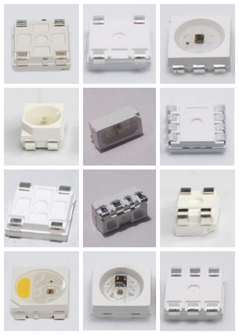
An SMD LED is a surface-mount light-emitting component. Some packages also contain control electronics; other strips use separate driver ICs on the PCB. Current regulation and individually addressable colour control are separate functions. The words “built-in IC” alone do not define both.
| Architecture | What to identify | Buyer check |
|---|---|---|
| Integrated digital LED | Light-emitting elements and control circuitry in one LED package | Exact device, revision, voltage, data format and addressable unit |
| LEDs with a separate driver IC | A driver on the strip PCB controls one or more LEDs | LEDs per controlled group, channel mapping and cut unit |
| Current-regulated strip | A circuit regulates LED current | Input supply requirements and supported dimming method; confirm addressability separately |
Manufacturer examples help distinguish these categories: Worldsemi lists WS2812-series digital LEDs, while its WS2801 and WS2811 families are LED driver ICs. NXP describes PCA9685 as an I²C LED controller. A PCA9685-driven board is a board-level control implementation, rather than evidence that the controller is inside an LED package. These examples explain architecture; confirm the components in the Y&T model being quoted.
2. Identify the control architecture before choosing a strip
2.1 Data protocol and controller
Ask for the exact protocol, timing requirements, input logic levels, pinout and data direction. A single-data-line system and a clock-plus-data system need matching controller outputs. An I²C control board cannot be substituted solely because it also controls LEDs. Check the controller firmware and approved device variant together.
2.2 Colour channels
Confirm whether the model provides RGB, RGBW, tunable white or another channel arrangement. Check channel order and the white-channel specification. A package size or an IC label does not establish the available colours.
2.3 Package size and strip dimensions
Specify PCB width, total assembly height, profile clearance, LED spacing and cut positions. Similar-looking packages can have different pinouts and electrical characteristics. Use the drawing for the exact order.
2.4 Installation requirements
State indoor or outdoor exposure, ambient conditions, enclosure and access for maintenance. Automotive, medical or wet-location projects require applicable component and complete-product evidence for the stated use. Choose from documented model capabilities.
2.5 Voltage, current and power
Distinguish a component rating from the finished strip input rating. Request the operating voltage, power per metre under stated conditions, maximum permitted run and recommended feed layout. Avoid selecting a supply from a generic current class.
2.6 Addressable unit and control functions
Confirm how many LEDs form one controlled pixel or segment, along with colour channels, brightness control and supported effects. Built-in current regulation, wireless connectivity and a sensor input are separate features that must be specified.
2.7 Light direction
Top-emitting and side-emitting assemblies need different placement and optical checks. Test the chosen strip in its profile or enclosure; obtain model-specific output and viewing-angle information where the project needs it.
3. Compare the specifications that affect the project
3.1 Integration and PCB space
Integration can simplify part of a circuit. Compare the complete design, including connectors, power distribution and protection, before estimating any space or cost saving.
3.2 Brightness control and timing
Verify resolution, update behaviour and PWM characteristics on the chosen model. For example, Worldsemi lists 8-bit WS2812 variants and NXP specifies 12-bit PWM for PCA9685. A universal 16-bit specification would be misleading. Test low-level dimming and camera use in the actual application.
3.3 Output, temperature and reliability
Compare measured lighting output and electrical input under stated test conditions. Request operating limits, mounting recommendations and reliability evidence for the assembly. The presence of an IC does not establish a common efficiency, service life or failure rate for all strips.
3.4 System size and data distribution
Agree on pixel count, outputs, frame requirements, cable layout and power feeds. Confirm expansion limits with the controller and strip specifications, then test the intended configuration.
4. Understand the complete strip assembly
4.1 LED and optical parts
Check the required colour or white-light specification, the profile and any cover or diffuser. An integrated control circuit does not replace an optical sample check.
4.2 Driver and control parts
The driver determines how the selected circuit controls its load. Confirm which functions are inside the LED package and which belong to external components or firmware. Use the exact drawing and component documentation for substitutions.
4.3 PCB, connections and enclosure
Review strip width, copper and connection requirements, mounting method and enclosure as an assembly. Component-level protection or qualification has a defined scope; ask for the relevant evidence for the supplied product.
5. Check what an integrated IC actually provides
5.1 Power supply and controller requirements
An integrated LED driver still needs a suitable power source. A programmable system also needs a compatible control signal. MEAN WELL’s application FAQ explains why supply selection depends on the LED load circuit and its drive mode. Have the strip, controller and supply checked together before connecting power.
5.2 Colour effects
Effects depend on the channels, addressable groups and controller. Include the required effect or a short demonstration reference in the enquiry, and approve a working sample.
5.3 Sensors and automatic operation
Specify any light sensor, temperature feedback or wireless requirement separately. Confirm the necessary hardware, firmware and integration work in the project scope.
5.4 Pixel spacing and visual result
Compare LED density with controlled-pixel density. Check the result at the intended viewing distance and with the intended diffuser, especially when smooth movement or a continuous line matters.
6. Match the strip to the installation
For decorative effects, prioritise control compatibility, pixel grouping and the sample appearance. For a white-light project, prioritise output, colour quality, dimming and mounting. For exposed installations, assess the complete enclosure, connections and documented environmental limits. Describe the project so that a suitable strip family can be proposed.
7. Validate claimed advantages with a sample
7.1 Circuit and total project cost
Compare the complete strip, controller, power feeds, connectors and installation work. Record the assumptions behind the quotation instead of applying a fixed saving percentage to every project.
7.2 Control performance
Use an agreed test sequence to check colour order, dimming, effects and operation after a power cycle. Confirm the actual controller configuration used for acceptance.
7.3 Assembly quality
Agree on workmanship criteria, inspection records, traceability and sample approval. Ask for evidence supporting any quoted yield or defect-rate claim for the relevant production process.
7.4 Update and response behaviour
Test the intended controller with the specified number of pixels and outputs. Component data rates alone do not establish the complete system’s visible response or camera performance.
7.5 Service life and warranty
Request lifetime evidence with test conditions for the selected model. Y&T provides a five-year warranty for LED strips, including custom strips, and three years for power supplies and accessories, subject to the quoted product and applicable installation terms. A warranty period and a projected operating life describe different things.
7.6 Sample-to-production approval
Document the approved model, controller settings, wiring, drawings and acceptance checklist before production. Confirm changes to the IC, firmware or strip construction against that approval.
8. Choose the supplier and the right product route
Ask the supplier to identify the proposed strip, control architecture, compatible accessories and document scope. For other strip requirements, browse Y&T’s LED products, RGB+white LED strips and constant-current 2835 LED strips. Confirm digital addressability for an exact model before ordering.
Use the custom LED strip enquiry route for a drawing or a special requirement. State the controller already selected and the functions required so feasibility and component compatibility can be checked.
9. FAQs about LED strips with built-in ICs
Does every IC-equipped LED strip support individual pixel control?
Confirm it on the chosen model. Current regulation and digital pixel control perform different jobs; specify the required controlled unit.
Can I use any RGB controller with an addressable LED strip?
Use a controller that supports the strip’s exact protocol, voltage and channel mapping. Review the wiring diagram and firmware configuration before testing.
Can a flexible LED strip with ICs be cut?
Use only the cut positions and connection method approved for that strip. Confirm whether the cut unit matches one pixel or a group, and how any enclosure must be resealed.
Does an integrated IC remove the need for a power supply?
The assembly needs a supply matched to its input requirements. Include power distribution and controller requirements in the system review.
How long will an IC-equipped LED strip last?
Request model-specific lifetime data with its test conditions. The type of IC does not establish the operating life of the complete strip.
What should I send to obtain an LED strip quotation?
Send the application, controller or protocol, voltage, total metres, individual run lengths, quantity, dimensions, colour requirements, destination and required date. Attach a drawing or installation photo if available.
10. Send an LED strip project brief
Y&T Technology Development Co.,Limited. has focused on LED lighting, especially LED strips, since 2012. Tell us whether you need a standard strip or a custom assembly, and which documents your project requires for the United States, Europe or Singapore. We will confirm model suitability and the quotation scope.
Standard LED strip MOQ is normally 5 metres / one roll; custom and accessory quantities are confirmed per project. Typical production is about 10 days for standard strips, about 10 days for custom samples and about 15 days for custom production after payment and specification confirmation. We normally produce to order. Urgent strip orders can be dispatched as fast as within three days after order placement when the model, quantity and rush schedule are confirmed; transport time is separate.
Send Your LED Strip Project Requirements
Technical references
The component and application references below support the architecture discussion. Confirm the actual components and document scope for the proposed Y&T strip.